Accurate component placement in Surface Mount Technology (SMT) assembly lines depends on one factor that is often underestimated: the quality of the illumination. Pick-and-place robots rely on machine vision cameras to locate component feeders, verify polarity, and confirm placement positions on PCB pads. When the lighting is inconsistent or poorly matched to the inspection geometry, the vision algorithm cannot extract reliable position data — and placement errors follow at full production speed.
SMD components range from 0201 passives (0.6 mm × 0.3 mm) to large BGAs and connectors. Each component type, each lead geometry, and each PCB surface finish requires a different illumination approach. A single ring light cannot cover all these inspection tasks. Understanding the optical interaction between the LED illuminator, the component, and the camera is the starting point for any reliable pick-and-place vision system design.

Möchten Sie Hilfe bei der Auswahl des Produkts?
Warum die Beleuchtung die Pick-and-Place-Genauigkeit bestimmt
A pick-and-place vision system performs two distinct inspection tasks. The first is component recognition: the camera must identify the component type, read its orientation, and confirm its position in the feeder tape pocket. The second is placement verification: after the nozzle deposits the component on the PCB, a verification camera checks that the component is correctly seated, centered on the pads, and in the expected orientation.
Both tasks require high-contrast images with sharp edges. Contrast depends directly on illumination. A component lead that appears bright and well-defined under one lighting geometry may become invisible against a reflective PCB copper background under different illumination. Selecting the wrong illuminator geometry or wavelength is the most frequent cause of false rejects and missed pick errors in SMT inspection systems.
Beleuchtungstechniken für die Inspektion von SMD-Bauteilen
Direkte Ringbeleuchtung
LED ring lights are the standard illumination choice for component-level pick-and-place vision. Mounted coaxially with the camera lens, they provide directional illumination from a well-defined angular range around the optical axis. This geometry produces consistent shadow patterns around component edges, enhancing edge contrast for template matching and centroid detection algorithms.
High-angle ring lights (45° to 90° from the optical axis) provide broad, uniform illumination across the component top surface. They are effective for reading component markings, verifying polarity indicators, and inspecting flat-topped packages. Low-angle ring lights direct light at grazing incidence to the PCB surface, enhancing lead coplanarity, solder joint geometry, and surface texture on pads.
Niedrigwinkel- und Darkfield-Beleuchtung für die Pin-Inspektion
Lead coplanarity inspection requires that small height differences between individual leads of a fine-pitch IC package are reliably detected. Low-angle (darkfield) illumination from a ring light at 10° to 20° from the PCB plane creates shadow and highlight patterns that make lead height variations clearly visible. A lead that is bent or lifted by even a fraction of a millimetre casts a characteristic shadow that the vision algorithm can detect.
The same low-angle technique is effective for detecting missing solder paste deposits, misaligned stencil prints, and raised solder balls on BGA packages. The contrast between the specular reflection from a correctly formed solder feature and the shadow from a defective one is maximised under grazing-incidence illumination.
Backlight-Beleuchtung für Bauteil-Silhouette und Dimensionsinspektion
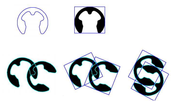
Backlight LED illuminators transmit diffuse light through a uniform emitting surface positioned behind the component. The camera captures the component silhouette — a high-contrast dark image of the component profile against a bright, uniform background. This technique is used for dimensional inspection of component lead pitch, body width, and lead length before placement.
Backlight silhouette imaging is also effective for verifying nozzle grip: the camera checks that the component is correctly seated on the pick nozzle, at the correct height and without tilt. The uniform background eliminates all surface texture and reflectivity variables, making the component boundary measurement independent of surface finish.
Koaxialbeleuchtung für flache, spiegelnde Oberflächen
Bare PCB copper pads and HASL-finished surfaces are highly specular. Conventional ring light illumination creates bright specular hot spots that obscure pad geometry. Coaxial (on-axis) illumination directs light along the same optical axis as the camera using a beamsplitter, eliminating specular reflection and revealing surface features uniformly across the full field of view.
Coaxial illumination is the preferred technique for PCB trace inspection, pad registration verification, and solder paste print quality control. It is particularly valuable on bare copper or ENIG PCB surfaces where high reflectivity renders other illumination geometries unsuitable.
Wellenlängenauswahl für PCB- und Bauteilinspektion
LED wavelength selection has a significant effect on image contrast in PCB inspection. Different wavelengths interact differently with PCB surface materials, solder alloys, and component marking inks.
Rote und Nahinfrarot-LEDs
Red LEDs (620-660 nm) and NIR LEDs (780-940 nm) penetrate the green PCB substrate, reducing background noise from glass-fibre texture. Red illumination improves contrast between solder and copper on HASL boards. NIR at 850 nm is effective for inspecting through conformal coating and reading codes on dark component bodies.
Blaue und UV-LEDs
Blue LEDs (450-470 nm) enhance contrast of fine features on green PCB substrates. UV LEDs at 365-385 nm excite fluorescence in solder flux residues and conformal coatings, making their distribution clearly visible. UV illumination is used in conformal coating inspection and flux residue verification after reflow and wave soldering.
Strobe-Beleuchtung für Hochgeschwindigkeits-SMT-Linien
Modern SMT pick-and-place machines operate at speeds exceeding 100,000 components per hour. Camera exposures must stay below 1 millisecond to avoid motion blur. Continuous LED illumination at the required brightness would exceed LED thermal limits and reduce service life.
A strobe controller fires the LED in a short pulse — typically 50 to 500 microseconds — synchronised with the camera trigger. LED current can be increased to two to five times the continuous rating during the pulse, delivering peak brightness for short-exposure imaging. RODER Vision LED illuminators are fully strobe-compatible, with stable peak output and microsecond-range trigger latency for precise SMT camera synchronisation.
Integrationsüberlegungen für SMT Pick-and-Place-Bildverarbeitung
Arbeitsabstand und Illuminator-Größe
Working distance in SMT systems is often constrained by nozzle and feeder geometry. The illuminator must fit within the available space around the lens without interfering with pick head motion. Ring lights with inner diameters matched to the lens barrel are preferred. For working distances below 30 mm, high-density LED ring lights or miniature spot illuminators provide the correct geometry.
Gleichmäßigkeit und Langzeitstabilität
Illumination uniformity directly affects centroid detection accuracy. A non-uniform illuminator creates intensity gradients that shift the apparent position of component edges, introducing systematic measurement errors. RODER Vision illuminators are designed for high spatial uniformity, with intensity variation across the emission surface verified during production.
Constant-current LED drivers maintain stable output regardless of supply voltage variation. The HTTM thermal management technology developed by RODER minimises LED junction temperature, extending illuminator lifetime and output stability in continuous production environments.
Produkte und Technologien
RODER Vision Beleuchtungsfamilien für SMT- und Pick-and-Place-Anwendungen
The following RODER Vision product families are the most suitable for electronic component pick-and-place vision, SMD inspection, and PCB quality control applications.

DC2 — Niedrigwinkel-LED-Ringbeleuchtungen
Grazing-incidence darkfield illumination for lead coplanarity, solder joint, and surface texture inspection. Reveals fine-pitch IC lead geometry invisible to standard ring lights.

DC4 — Hochintensive LED-Ringbeleuchtungen
High-intensity direct ring illumination for component recognition, polarity verification, and marking readability. Strobe-compatible for high-speed SMT camera synchronisation.

BL2 — LED-Backlight-Beleuchtungen
Uniform backlight for component silhouette, lead pitch, body dimension, and nozzle grip verification. Eliminates surface reflectivity variables from dimensional measurement.

DL3M — Miniatur-Spot-LED-Beleuchtungen
Ultra-compact format for space-constrained pick-and-place head integration. Multi-wavelength options for component marking readability and UV fluorescence inspection.
Häufig gestellte Fragen
High-intensity LED ring lights are the standard solution. They mount coaxially with the camera lens and provide consistent directional illumination for component edge contrast. Low-angle ring lights are preferred for lead coplanarity and solder joint inspection.
SMT machines run at over 100,000 components per hour. Camera exposures must stay below 1 millisecond to avoid motion blur. Strobe pulses the LED at peak current during camera exposure, delivering the required brightness for short exposures without exceeding thermal limits.
Backlight illuminators are used for component silhouette inspection, dimensional measurement, lead pitch verification, and nozzle grip confirmation. The uniform bright background eliminates surface reflectivity variables.
Red LEDs 620-660 nm improve solder/copper contrast. Blue LEDs 450-470 nm enhance contrast on green PCB substrates. UV at 365-385 nm reveals flux residues. NIR at 850 nm inspects through conformal coatings.
Incorrect illumination reduces edge contrast and creates non-uniform images, causing inaccurate component position readings. Correct illumination selection is the most effective way to reduce false reject rates.
Kontakte & Informationen
Kontakt für allgemeine Informationen : info@roder.it
Partner für System- und Sensorintegration : www.roder.it
RODER Bildverarbeitungs-Abteilung : www.rodervision.com
RODER Abteilung Messinstrumente : www.innovacheck.com
Mehr Informationen über RODER VISION : about us
Die Informationen auf dieser Website dienen ausschließlich Informationszwecken. Obwohl sie mit größter Sorgfalt erstellt wurden, stellen sie kein vertragliches Angebot und keine verbindliche Lieferverpflichtung dar. Sie können Übertragungs-, Übersetzungs- oder Tippfehler enthalten. Für präzise und aktuelle Informationen wenden Sie sich bitte direkt an unser Unternehmen.
Bitte beachten Sie: Einige Bilder auf dieser Website wurden absichtlich mittels Künstlicher Intelligenz (KI) generiert. Dies liegt daran, dass es bei vielen Anwendungen und Projekten aufgrund von Vertraulichkeitsvereinbarungen, Vertragsklauseln und Geheimhaltungsvereinbarungen (NDAs) nicht möglich ist, Fotografien der tatsächlichen Anlage oder des Systems zu veröffentlichen.
Related topics :
 Maximierung der Pick-&-Place-Genauigkeit: die Schlüsselrolle des Backlights.
 Integration von LED-Beleuchtung in automatische Maschinen: Lösungen für die Teilebeladung.
 High-Speed Vision on Conveyor Belts: Achieving Uniformity with RODER LED Illuminators.
 SCARA Robotics and Shape Recognition: Simplifying Complex Silhouette Detection with LED backlight.
 LED Illumination for PCB and Electronics Inspection: Soldering, Components and Trace Verification