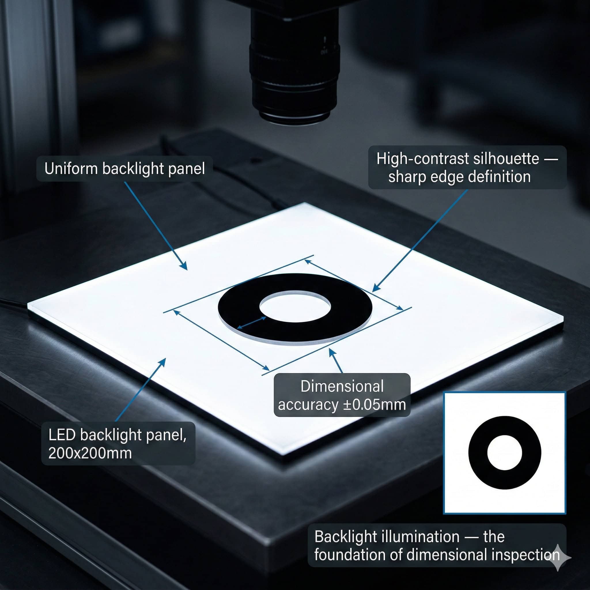
Backlight illumination places the light source behind the object being inspected and directs it toward the camera. The object appears as a dark silhouette against a bright, uniform background. This technique produces some of the highest contrast images achievable in machine vision, making it ideal for dimensional measurement, edge detection, and transmission-mode inspection of transparent or semi-transparent materials.
Unlike reflected illumination techniques where surface texture, colour, and reflectance all affect the image, backlight silhouette imaging is largely insensitive to the surface properties of the object. The edge of the object is defined by the boundary between the bright background and the dark object silhouette. This boundary is sharp, high-contrast, and repeatable across different batches and surface finishes of the same part type.
How Backlight Illumination Works
A backlight illuminator consists of an LED array and a diffuser panel. The LEDs generate the illumination. The diffuser spreads the light from the individual LED emitters into a uniform, extended area source. The object is placed between the diffuser and the camera. The camera images the diffuser through the object, seeing the bright diffuser wherever the object does not block the light, and a dark silhouette where the object is present.
The key performance parameter of a backlight is luminance uniformity. Uniformity describes how consistent the brightness is across the active area of the backlight. A uniformity of 95% means the darkest point on the active surface is at least 95% as bright as the brightest point. High uniformity is essential for accurate edge detection because a non-uniform background creates apparent brightness gradients that shift the perceived edge position.

Do you want help choosing the product?
Silhouette Mode vs. Transmission Mode
Backlight illuminators are used in two distinct inspection modes: silhouette mode and transmission mode.
Silhouette Mode: Dimensional Gauging and Edge Detection
In silhouette mode, the object is opaque and the inspection relies on the outline of the object against the bright background. The camera measures the position of the silhouette edges to determine the object dimensions. This is used for go/no-go gauging of machined parts, diameter measurement of cylindrical components, profile measurement of stamped or moulded parts, and detection of missing features such as holes or tabs.
Silhouette mode is highly accurate because the edge contrast is very high. Sub-pixel edge detection algorithms can locate the edge position with accuracy better than 0.1 pixel under good illumination conditions. For a camera with a pixel size corresponding to 10 micrometres at the object plane, this means dimensional measurement repeatability better than 1 micrometre.
Transmission Mode: Transparent and Semi-Transparent Materials
In transmission mode, the object transmits some of the backlight illumination. The camera sees spatial variation in the transmitted intensity, which is used to detect internal features, inclusions, contamination, or structural defects that affect transmission. This is used for inspection of glass sheets, plastic films, pharmaceutical tablets, and semiconductor wafers.
Transmission mode inspection requires a backlight with very high uniformity because any non-uniformity in the background illumination is interpreted as a feature of the object. The illumination wavelength may also matter. Some defects in transparent materials are only visible at specific wavelengths. RODER Vision BL-series backlights are available in multiple wavelengths including UV, blue, green, red, and near-infrared to support wavelength-specific transmission inspection.
Diffuser Types and Their Effect on Uniformity
The diffuser is the optical element that determines the uniformity of the backlight output. Three main diffuser types are used in machine vision backlights.
Opal Diffusers
Opal diffusers are translucent white panels that scatter light through bulk diffusion. They provide smooth, uniform output but reduce the total luminance because much of the light is scattered backward toward the LED source rather than forward toward the camera. Opal diffusers are cost-effective and produce excellent uniformity, but at lower overall brightness than direct or engineered diffuser designs.
Engineered Diffusers
Engineered diffusers use structured microoptical surfaces to control the angular distribution of the emitted light more precisely than opal diffusers. They can achieve higher uniformity at higher luminance than opal designs because they direct more of the available light in the forward direction. Engineered diffusers are used in RODER Vision high-uniformity BL-series backlights where both brightness and uniformity are critical.
Direct Illumination Designs
Some backlight designs use a high-density LED array without a separate diffuser, relying instead on the close spacing of the emitters and a short working distance to achieve acceptable uniformity. These designs achieve higher peak luminance than diffused designs but typically have lower uniformity. They are used where maximum brightness is the primary requirement and uniformity is of secondary importance.
Uniformity Specifications: What the Numbers Mean
Backlight uniformity is specified as a percentage. Common specifications are 90%, 95%, and 98% uniformity. These figures describe the ratio of the minimum to maximum luminance measured across the active area of the backlight, expressed as a percentage.
For dimensional gauging applications, uniformity below 90% is generally problematic. The apparent edge position shifts as the background brightness varies. A 10% uniformity variation can produce edge position errors of several pixels in a bright-to-dark transition, depending on the edge detection algorithm used.
For transmission mode inspection of transparent materials, 95% or better uniformity is typically required. Features that reduce transmission by only a few percent must be detectable against a uniform background. If the background itself varies by 5% or more, small transmission anomalies become difficult to distinguish from background non-uniformity.
Sizing a Backlight for Your Application
Active Area and Field of View
The active area of the backlight must be at least as large as the field of view of the camera at the object plane. If any part of the camera field of view falls outside the active area of the backlight, that region of the image will be dark. This makes it impossible to detect object edges in that region.
In practice, the active area of the backlight should be larger than the field of view by a margin that accounts for optical alignment tolerances and for the penumbra region at the edges of the backlight where uniformity may be lower. A margin of 10% to 20% on each side is typical.
Working Distance and Magnification
The object is typically placed close to the backlight surface to minimise penumbra effects at the object edges. Penumbra occurs because the backlight is an extended area source. Different parts of the source illuminate the object from slightly different angles. At the edge of the object, the transition from illuminated to shadowed is gradual rather than sharp. This gradual transition — the penumbra — reduces edge sharpness and measurement accuracy.
Placing the object as close as possible to the backlight surface minimises the penumbra width. For high-precision gauging applications, the object-to-backlight distance should be less than 10 mm when possible.
Multi-Wavelength Backlights for Transmission Inspection
Some transmission inspection applications benefit from illumination at specific wavelengths rather than white light. Glass defects may be more visible at UV or blue wavelengths. Plastic film inclusions may show better contrast at near-infrared wavelengths where the film is partially transparent. Pharmaceutical tablet inspection may use specific wavelengths where the active ingredient has distinctive absorption characteristics.
RODER Vision BL-series backlights are available in multiple single wavelengths as well as in white. This allows the engineer to select the wavelength that maximises the contrast of the target defect in the transmission image. A camera with the appropriate spectral sensitivity — enhanced blue sensitivity for UV or blue illumination, or NIR-sensitive sensor for NIR illumination — must be specified in combination with the wavelength-specific backlight.
Integration with Conveyor Systems
Backlight illuminators for inline inspection on conveyor systems are typically mounted below the conveyor belt. The conveyor belt must be transparent or have a transparent section aligned with the inspection zone. The object travels over the transparent section, the backlight illuminates it from below, and the camera images it from above.
Alternatively, the backlight can be mounted above the conveyor with the camera below, for applications where the object underside is the relevant inspection surface. In either configuration, the backlight must be triggered in synchronisation with the camera exposure to ensure consistent illumination across all frames. RODER Vision BL-series backlights support digital trigger inputs for synchronised strobe operation.
Products and Technologies
RODER Vision BL-Series Backlight Illuminator Families
The BL-series covers a range of sizes, uniformity levels, and wavelength options for silhouette and transmission inspection applications. All are manufactured in Italy to ISO 9001 standards with 48-hour burn-in testing.

BL3 — LED Backlight Series
High-uniformity backlight for dimensional gauging and silhouette inspection. Multiple sizes and wavelengths. IP65 option. Strobe trigger compatible.

DL6 — High Density LED Matrix
High-intensity front illumination complement to backlighting. Used for combined silhouette and surface inspection. HTTM thermal stability. Multi-wavelength.

DC6 — High Density LED Ring
Coaxial ring illumination for combined backlight and surface inspection stations. Compact. Multi-wavelength. Ideal for mixed gauging and surface verification tasks.

FD2 — Flat Dome LED Illuminators
Shadowless diffuse front illumination for reflective parts requiring both silhouette and surface inspection in the same station. Multiple sizes available.
Frequently Asked Questions
In silhouette mode, the object is opaque and the inspection uses the outline of the object against the bright background to measure dimensions and detect contour defects. In transmission mode, the object is transparent or semi-transparent and the inspection detects spatial variation in the transmitted light intensity, which reveals internal features, inclusions, or structural defects within the material.
For dimensional gauging, backlight uniformity of 90% or better is generally required as a minimum. At lower uniformity levels, the apparent edge position shifts as the background brightness varies, introducing systematic measurement errors. For precision gauging with sub-pixel accuracy requirements, 95% or better uniformity is recommended. For transmission mode inspection of transparent materials with small defects, 95% uniformity or better is typically required.
The object should be as close as possible to the backlight surface to minimise the penumbra at the object edges. Penumbra occurs because the backlight is an extended area source, creating a gradual rather than sharp transition at the object edge. For precision dimensional gauging, the object-to-backlight distance should be less than 10 mm. As the distance increases, the penumbra width increases and edge measurement accuracy decreases.
RODER Vision BL-series backlight illuminators are available in multiple wavelengths including UV (365 nm), blue (470 nm), green (525 nm), red (617 nm), near-infrared (850 nm, 940 nm), and white. The choice of wavelength depends on the inspection task. Some defects in transparent materials are only detectable at specific wavelengths where the target material has distinctive absorption or transmission characteristics.
Yes. Backlight illuminators for inline conveyor inspection are mounted below the conveyor belt. The belt must have a transparent section aligned with the inspection zone. The backlight illuminates the object from below and the camera images from above. The backlight is triggered in synchronisation with the camera exposure. RODER Vision BL-series backlights support digital trigger inputs for synchronised strobe operation on high-speed conveyor lines.
More information and contacts
Systems and Sensor Integration Partners : www.roder.it
Artificial Vision Division : www.rodervision.com
More information about RODER VISION : about us
Contact for general information : info@roder.it
The information on this website is provided for information purposes only. Although it has been prepared with the utmost care, it does not constitute a contractual offer or a binding commitment to supply. It may contain transcription, translation or typographical errors. For precise and up-to-date information, please contact our company directly.
Related topics :
 Backlight LED illuminators for shadow-based vision systems
 Profile and edge inspection on wooden products using LED backlighting
 Glass and PET bottle inspection: how to ensure compliance with LED backlights.
 Precision Bottle Cap Inspection: Machine Vision & LED Lighting Solutions
 The Advantages of LED Backlighting in Precise Dimensional Measurement