


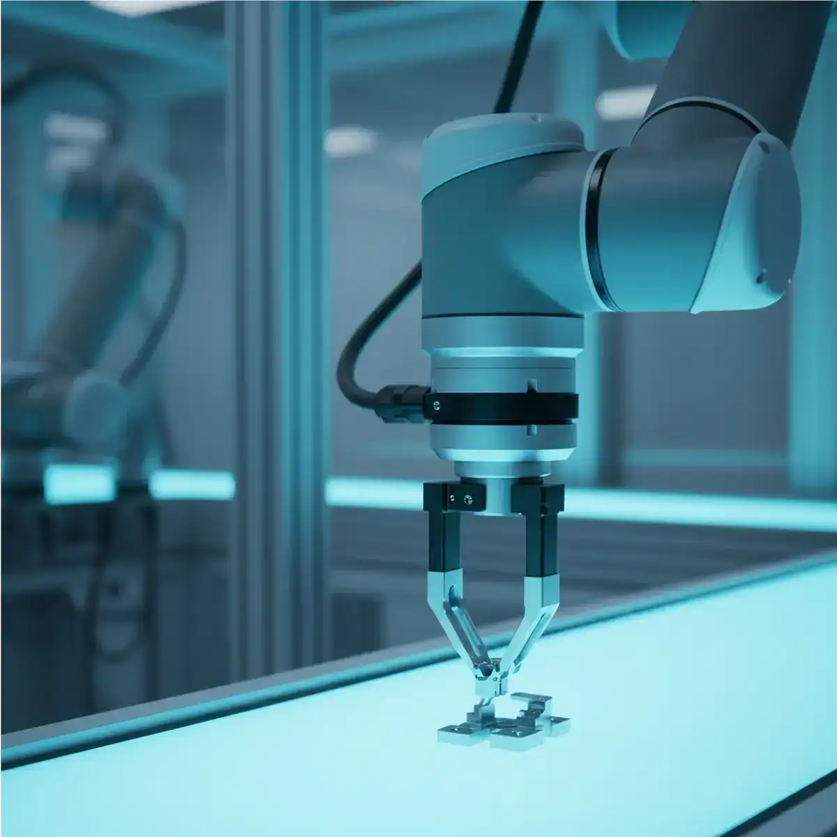
Robot guidance applications expect vision systems to return accurate, repeatable pose estimates at production speed. The camera only ever sees what the light reveals. When illumination wavers—through ambient light interference, thermal drift, or the wrong geometry—the vision algorithm is fed ambiguous image data, and robot placement errors follow close behind. Picking and positioning the right LED illuminator matters just as much as choosing the camera and lens in any robot vision system.
The three main families of robot guidance application—pick-and-place from a defined feeder or fixture, bin picking from a randomly filled container, and collaborative robot (cobot) guidance in shared workspaces—each place different demands on the illumination system. Working distance, part geometry, ambient light, safety constraints, and imaging modality all steer the correct illuminator choice.

Do you want help choosing the right product?
Why Steady Lighting Is Critical for Robot Pose Estimation
Robot pose estimation algorithms—whether rule-based template matching or deep-learning detection—work out a part’s position and orientation from image features. How reliable that calculation is depends on the contrast, sharpness, and repeatability of those features in the image, and illumination directly governs all three.
Any shift in illumination intensity, colour temperature, or spatial distribution between calibration and production makes the feature set the algorithm sees diverge from the training or reference data. That shows up as higher localisation uncertainty, more pick failures, and lower throughput. In practice, the most common source of robot vision instability in production is not the algorithm—it is lighting drift or ambient light contamination.
2D Robot Guidance: Area Scan Cameras and Direct LED Illumination
Two-dimensional robot guidance systems use area scan cameras to grab a top-down or angled image of the part. The vision algorithm computes the 2D position and rotation of the part within the field of view, and the robot corrects its approach trajectory on that basis before picking.
Ring Lights for Pick-and-Place Vision
LED ring lights are the most widely used illumination for 2D pick-and-place robot guidance. Mounted coaxially with the camera lens, a ring light casts directional light from a steady angular position relative to the camera’s optical axis. This geometry yields repeatable shadow patterns that lift part-edge contrast for template matching and feature extraction.
Low-angle ring lights send light in at grazing incidence to the part surface, drawing out surface texture and edge relief. The technique works well on parts with raised features, logos, or surface markings that set the pick orientation. For flat, smooth parts on diffuse backgrounds, high-angle ring lights or direct matrix illuminators give more uniform field illumination and better overall contrast.
Bar Lights and Matrix Illuminators for Large Fields of View
When the robot picks from a wide conveyor or pallet area, a single ring light cannot light the full field of view evenly. Bar lights or large-format matrix LED illuminators set at controlled angles supply the uniform, directional light needed across extended fields. Several bar lights arranged symmetrically around the field cancel the directional shadow asymmetries that drive orientation errors in vision algorithms.
3D Robot Guidance: Structured Light and Pattern Projection
Three-dimensional robot guidance systems recover a part’s full 6-DOF pose—position in X, Y, Z plus rotation about three axes. That capability is needed for picking parts from fixtures, trays, or mixed-orientation presentations where 2D guidance cannot resolve ambiguity in depth or tilt.
Structured light 3D systems project a known pattern—typically fringe patterns, grids, or coded light sequences—onto the part surface. A camera captures how the projected pattern distorts over the part geometry, and a reconstruction algorithm builds the 3D point cloud. Illumination for structured light has to deliver high contrast between the projected pattern and the part background, which calls for a high-intensity, stable LED projector with a narrow emission angle.
For time-of-flight (ToF) and active stereo 3D sensors, LED illuminators in the near-infrared (NIR) band—typically 850 nm or 940 nm—project the reference pattern. The camera carries a narrowband optical filter matched to the illuminator wavelength to shut out ambient light. High-power NIR LED illuminators with stable peak output are essential for dependable 3D reconstruction at robot guidance distances.
Bin Picking: Illumination for Random Pile Inspection

Bin picking asks the vision system to locate and identify individual parts inside a randomly filled container, with parts at arbitrary orientations, partly occluded, and at varying heights. From an illumination standpoint, it is the most demanding robot guidance application of all.
Illumination Challenges in Bin Picking
Parts in a bin throw up several problems at once. Metallic parts kick back specular reflections from any directional light. Overlapping parts create tangled shadow patterns. The vertical depth across a bin may span 200 mm or more, which swings illumination intensity and shadow geometry across the working volume. No single illumination geometry settles all of these for every part type.
For 3D bin picking systems, the structured light projector or active stereo illuminator has to give enough contrast for reliable 3D reconstruction over the full bin depth. High-power LED matrix illuminators with adjustable intensity let the integrator tune the light level to each bin geometry and part reflectivity. Diffuse or dome illumination is often combined with the 3D sensor to tame specular artefacts on metallic parts.
Combining Illumination Modes for Robust Bin Picking
Many production bin picking cells run several light sources in sequence. A structured light projector captures the 3D scene for part localisation, while a separate directional LED illuminator fires during 2D image capture for grasp point selection and quality checks. This multi-stage approach tunes each lighting condition on its own.
Collaborative Robot Lighting: Safety, Form Factor, and Flicker-Free Operation
Collaborative robots share their workspace with human workers. Lighting for cobot vision systems has to meet requirements that never arise in fully guarded cells: photobiological safety, a compact form factor that suits the cobot end-of-arm tool, and flicker-free operation that causes no discomfort or hazard to nearby operators.
Photobiological Safety for Cobot Lighting
LED illuminators used close to human workers must meet IEC 62471 photobiological safety limits. That standard sets Risk Group 0 (exempt), Risk Group 1 (low risk), and Risk Group 2 (moderate risk) classes from measured optical radiation levels. For cobot work, Risk Group 0 or Risk Group 1 illuminators keep operators safe without extra protective barriers.
High-intensity blue LED illuminators at short working distances can pose a blue light hazard and have to be checked against IEC 62471 limits before deployment. Infrared illuminators beyond 780 nm are invisible to the eye and never trigger the blink reflex, so their emitted power needs particular care against the IEC 62471 infrared radiation limits.
Flicker-Free LED Operation for Human-Cobot Environments
LED illuminators driven at mains frequency (50 or 60 Hz) or at low PWM frequencies throw a visible flicker that tires the eyes of nearby workers. In shared workspaces, LED illuminators should run in true DC continuous mode with regulated constant-current drivers, or in high-frequency PWM above 1 kHz that lifts flicker beyond the human perception threshold.
Robot-Mounted vs. Fixed Lighting: Pros and Cons
Illuminators for robot guidance can ride on the robot end-of-arm tool (EOAT), moving with the camera, or stay fixed relative to the workspace. Each mounting strategy carries its own advantages and limits that shape system design decisions.
End-of-Arm Mounted Illumination
EOAT-mounted illuminators hold a constant geometric relationship between light source, camera, and part surface no matter where the robot moves, which keeps the illumination geometry consistent across the workspace. The trade-offs are size and weight: illuminators for EOAT mounting have to stay compact and light to fit within the robot payload budget. Routing the cable to a moving EOAT also needs careful handling to head off fatigue failures over the illuminator service life.
Fixed Illumination
Fixed illuminators sit at a defined spot in the robot cell, and the robot brings the part or camera to the lit zone for image capture. Fixed illumination frees the illuminator from robot payload limits, making room for larger, higher-power units. For well-defined pick positions and single-zone illumination, fixed mounting is simpler and more reliable.
Ambient Light Rejection in Robot Vision Cells
Factory ambient light—from overhead fixtures, welding arcs, or sunlight through skylights—contaminates robot vision images whenever its intensity rivals the LED illuminator output at the part surface. Effective rejection strategies include high-intensity strobed LED illuminators that overpower ambient light during the camera exposure; darkfield hoods or shrouds enclosing the capture zone; narrowband LED illuminators paired with matching bandpass filters on the camera lens; and NIR illumination at 850 nm or 940 nm, where factory ambient light levels run lower than in the visible spectrum.
Products and Technologies


Frequently Asked Questions
LED ring lights are the standard choice for 2D pick-and-place robot vision. Mounted coaxially with the camera lens, they give steady directional light for part edge and feature detection. Low-angle ring lights bring out surface relief, while high-intensity strobe ring lights suit fast pick cycles.
Use high-intensity strobed LED illuminators that overpower ambient light during the camera exposure, enclose the capture zone with a darkfield hood, pair a narrowband LED with a matching bandpass filter on the camera lens, or choose NIR illumination at 850-940 nm where factory ambient light is lower.
Structured light systems need high-intensity LED projectors for high-contrast pattern projection, while active stereo and ToF sensors use NIR LED illuminators. Diffuse or dome illumination cuts specular reflections on metallic parts, and high-power matrix illuminators with adjustable intensity are preferred to tune the level to each bin.
LED illuminators must meet IEC 62471 photobiological safety limits. Risk Group 0 or 1 illuminators suit cobot applications with human operators, and high-frequency PWM above 1 kHz or true DC operation avoids visible flicker for nearby workers.
EOAT mounting keeps the illumination geometry constant but needs compact, lightweight illuminators within payload limits. Fixed mounting allows larger, more powerful illuminators but needs defined pick positions. Fixed is simpler for single-zone work, while EOAT suits flexible multi-position guidance.
Contacts & Information
Contact for general information : info@roder.it
Systems and Sensor Integration Partner : www.roder.it
RODER Artificial Vision Division : www.rodervision.com
RODER Instruments Division : www.innovacheck.com
More information about RODER VISION : about us
The information on this website is provided for informational purposes only. Although it has been prepared with the utmost care, it does not constitute a contractual offer or a binding commitment to supply. It may contain transcription, translation, or typographical errors. For precise and up-to-date information, please contact our company directly.
Please note: Some images on this website have been intentionally generated using Artificial Intelligence (AI). This is due to the fact that, for many applications and projects, it is not possible to disclose photographs of the actual installation or system due to confidentiality agreements, contractual clauses, and Non-Disclosure Agreements (NDAs).
Related topics :
 SCARA Shape Recognition: Simplifying Silhouette Detection with LED Backlight
 Embedding LED Illuminators in Automatic Machines for Reliable Part Loading
 Improving Part Orientation in Vibratory Feeders with LED Vision Lighting
 High-Speed Conveyor Vision: Uniform Lighting for Delta Robots with RODER LED Illuminators