Application notes are the most direct form of technical knowledge transfer in machine vision engineering. A datasheet tells you what an illuminator can do. An application note tells you how it actually performed on a real production line, with a real part, under real constraints.
At RODER Vision, every illuminator in the product range is the fruit of years of hands-on application engineering. The notes gathered here document specific inspection challenges, the lighting configurations used to solve them, and the results achieved. They are written for vision engineers, system integrators, and OEM designers who need to move quickly from a problem statement to a working optical configuration.
Why Application Notes Matter More Than Datasheets
Datasheets define the nominal performance of a component. They specify luminous intensity, beam angle, wavelength, power supply range, and mechanical dimensions. All of this is necessary, but none of it tells you whether a given illuminator will produce enough contrast on a scratched aluminium surface at a working distance of 120 mm with a 25 mm lens.
Application notes fill that gap. They turn product specifications into inspection outcomes. Each note describes the part being inspected, the defect or feature of interest, the camera and lens configuration, the illumination geometry chosen, and the result in terms of contrast, detection rate, or cycle time. Engineers reading an application note can immediately judge whether their own problem is similar enough to apply the same approach.

Do you want help choosing the product?
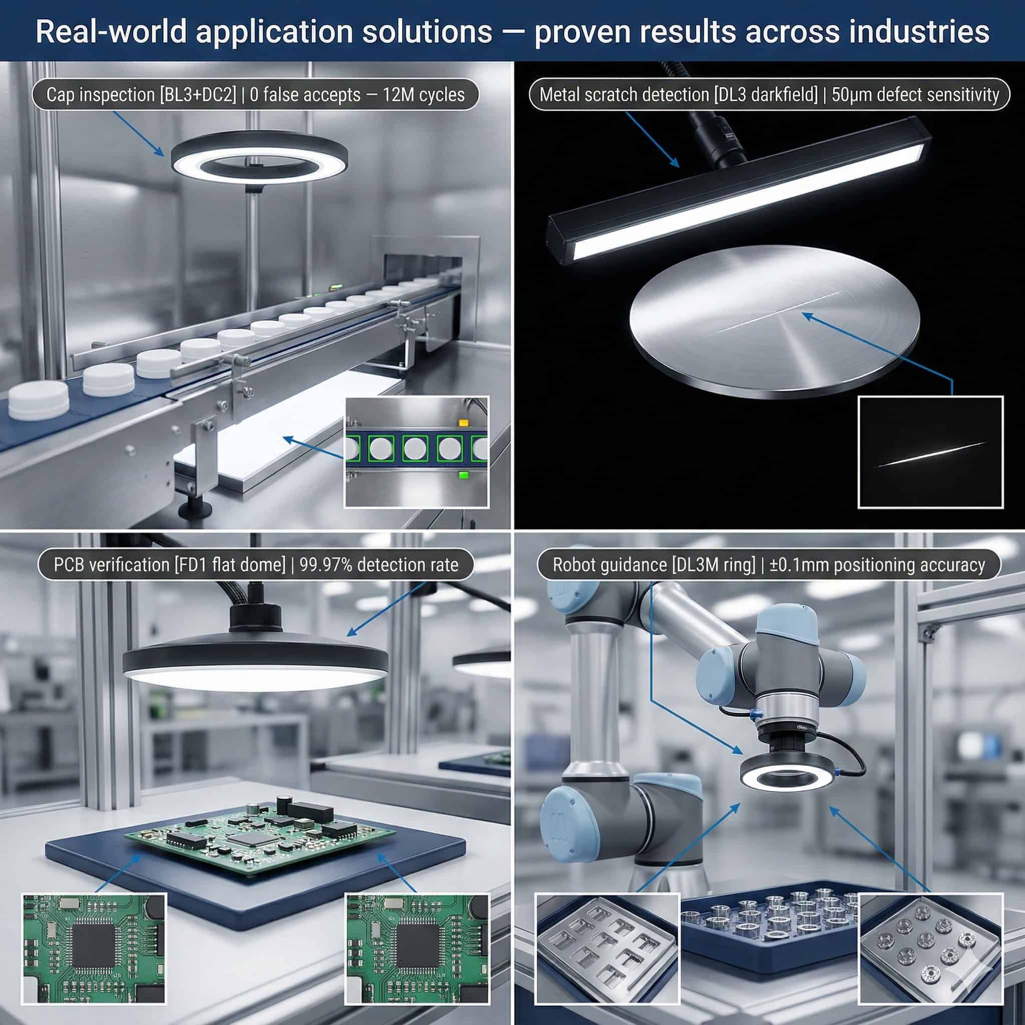
Application Category: Cap and Closure Inspection
Cap and closure inspection is one of the most common machine vision tasks in food, beverage, and pharmaceutical manufacturing. The inspection objectives usually include presence verification, correct seating, cap colour, tamper-evident ring integrity, and print legibility on the cap surface.
The illumination challenge is significant. Caps are often glossy, curved, and presented at varying orientations on a moving conveyor. Specular reflections from glossy plastic or aluminium surfaces can hide the features the system needs to detect. A high-angle ring illuminator throws a bright specular highlight in the centre of the cap, masking any defects there. The solution in most cases is a combination of diffuse dome illumination to hold down reflections and a low-angle darkfield ring to reveal surface texture and embossed characters.
RODER Vision DC-series ring illuminators, particularly high-density models, suit this application well. Their compact form factor allows integration close to the inspection point on high-speed lines. The availability of multiple wavelengths lets engineers tune contrast for cap colour without changing the mechanical setup.
Application Category: Surface Defect Detection on Metals
Metal surface inspection covers a wide range of industrial parts: stamped steel panels, turned aluminium components, sintered parts, extruded profiles, and machined surfaces. The defects of interest include scratches, pitting, cracks, inclusions, and machining marks.
The key illumination principle for surface defect detection on metals is angle of incidence. Defects recessed into the surface—scratches, pits, cracks—scatter light differently from the surrounding surface when lit at a grazing angle. That is the basis of darkfield illumination. A low-angle ring or bar illuminator placed close to the part surface creates a bright specular background on flat areas and reveals defects as bright features against a dark background, or as dark features against a bright one, depending on geometry.
For cylindrical parts, axial or coaxial illumination may be needed for uniform coverage around the circumference. For flat panels, a large-format matrix illuminator in grazing incidence configuration is often the most practical approach. RODER Vision DL-series matrix illuminators are designed for exactly this kind of large-field, high-intensity application.
Illumination Angle and Defect Visibility
The relationship between illumination angle and defect visibility is non-linear. A small change in angle can shift a defect from invisible to clearly detectable. For this reason, RODER Vision application notes for metal surface inspection always document the exact illuminator-to-surface distance, the illuminator tilt angle if relevant, and the resulting image contrast ratio measured on a calibration artefact.
Application Category: Dimensional Gauging with Backlight
Dimensional gauging with backlight is used when the inspection task has to measure the outline or profile of a part with sub-pixel accuracy. Common examples include connector pin length verification, seal ring profile measurement, tube wall thickness measurement, and hole diameter gauging on flat parts.
Backlight illumination places the part between the camera and a uniform, high-luminance light source. The part reads as a dark silhouette against a bright background. Edge detection algorithms can locate the part boundary with very high repeatability, limited mainly by the resolution of the camera and the spatial coherence of the light source.
The critical parameter for backlight selection in gauging applications is luminance uniformity. A non-uniform backlight introduces brightness gradients across the image that shift the apparent position of the edge and add measurement errors. RODER Vision BL-series backlights are specified with luminance uniformity values measured across the active surface, giving engineers the data they need to judge suitability for their gauging tolerance requirements.
Application Category: Barcode and OCR Reading
Industrial barcode reading and optical character recognition (OCR) are often treated as software problems. In practice, they are frequently lighting problems. A barcode reader or OCR algorithm performs reliably only if the image contrast between the dark and light elements of the code or character is sufficient and consistent across the entire field of view.
The main illumination challenges for barcode and OCR reading are reflective substrates, curved surfaces, and variable print quality. Specular reflections from a glossy label or embossed plastic can throw localised bright spots that saturate the sensor and make the underlying code unreadable. Coaxial illumination, which sends light along the optical axis of the camera, is often effective for flat, reflective surfaces because specular reflections return directly to the camera and the code elements read at a uniform brightness level.
For curved surfaces such as cylindrical cans or bottles, a line-scan configuration with a bar or line illuminator matched to the camera frame rate is usually used. The illuminator has to give consistent intensity across the full scan width without hot spots or falloff at the edges.
Application Category: Robot Guidance and Pick-and-Place
Robot guidance applications use machine vision to work out the position and orientation of a part so a robot arm can pick it correctly. The inspection task is usually a location measurement rather than a defect detection task, but the illumination requirements are no less critical.
The main requirement for robot guidance illumination is repeatability. The vision system has to return the same position measurement for the same part in the same position, whatever the ambient light changes, shift changes, or seasonal variation in factory lighting. That calls for an illuminator with enough intensity to dominate ambient light and a stable output that does not drift over time or with temperature.
RODER Vision illuminators build in HTTM (High Thermal Transfer Module) technology, which actively manages heat at the LED junction to hold photometric output stable over the operational lifetime of the product. For robot guidance applications, that translates straight into long-term repeatability of the vision system without recalibration.
Application Category: Conveyor and In-Line Inspection
In-line inspection on conveyor systems brings specific constraints absent in static inspection cells. The part is moving, usually at speeds between 0.5 and 3 metres per second. The illuminator has to give enough intensity to allow short exposure times that freeze motion without blur. The illuminator geometry has to suit the conveyor structure, often calling for low-profile or side-mounted configurations.
Strobe illumination is frequently used on high-speed conveyors. A short, intense pulse of light—typically between 10 and 500 microseconds—is synced with the camera trigger to capture a sharp image of the moving part. RODER Vision illuminators support both continuous and strobe operating modes, with driver electronics that deliver peak currents well above the continuous rating for short pulse durations.
The combination of high peak intensity, accurate trigger synchronisation, and stable thermal management makes RODER Vision illuminators reliable components in demanding conveyor inspection installations across automotive, food processing, logistics, and electronics manufacturing.
Products and Technologies
RODER Vision Illuminator Families for Application Note Topics
The illuminator families below are the most frequently referenced in RODER Vision application notes. Each family addresses a distinct set of inspection geometries and application requirements.

DC6 — High Density LED Ring
Compact ring illuminator for cap, connector, and circular part inspection. Multi-wavelength. Ideal for brightfield and darkfield configurations.

BL3 — LED Backlight Illuminators
High-uniformity backlight for dimensional gauging, profile inspection, and silhouette-based measurements requiring sub-pixel edge accuracy.

DL5 — High Intensity LED Matrix
High-intensity matrix illuminator for surface defect detection and conveyor inspection. Supports strobe mode for high-speed line applications.

DL6 — High Density LED Matrix
Dense LED matrix for barcode/OCR reading, flat surface inspection, and robot guidance. Available in UV, visible, and NIR wavelengths.
Frequently Asked Questions
An application note is a technical document that describes a real inspection problem, the illumination and camera configuration used to solve it, and the results achieved. It is more specific than a datasheet and more practical than a product brochure. Application notes help engineers pick the right illuminator for their inspection task without extensive trial and error.
Darkfield or low-angle illumination is the most effective technique for surface defect detection on metals. Light is directed at a grazing angle to the surface. Flat areas reflect light away from the camera and read dark. Raised or recessed defects such as scratches, pits, or cracks scatter light toward the camera and read bright. The result is high contrast between the background and the defect.
Brightfield illumination is best for inspecting features defined by surface colour, print, or geometry at normal incidence. Darkfield illumination is best for catching surface texture anomalies such as scratches, cracks, or embossed characters. In practice, many applications gain from testing both configurations before committing to a final design.
HTTM (High Thermal Transfer Module) is RODER Vision’s proprietary thermal management technology. It holds the LED junction temperature stable during continuous operation. A stable junction temperature means stable luminous flux, which means the illuminator produces the same light intensity on day one and after three years of continuous use. For inspection systems calibrated once and expected to run without recalibration, this is a critical performance requirement.
Yes. Strobe illumination is the standard approach for high-speed conveyor inspection. A short pulse of high-intensity light is synced with the camera trigger to freeze the motion of the part and produce a sharp image. RODER Vision illuminators support strobe mode with peak currents well above the continuous rating. The pulse duration and frequency have to be chosen to match the conveyor speed, part size, and camera frame rate.
Contacts & Information
Contact for general information : info@roder.it
Systems and Sensor Integration Partner : www.roder.it
RODER Artificial Vision Division : www.rodervision.com
RODER Instruments Division : www.innovacheck.com
More information about RODER VISION : about us
The information on this website is provided for informational purposes only. Although it has been prepared with the utmost care, it does not constitute a contractual offer or a binding commitment to supply. It may contain transcription, translation, or typographical errors. For precise and up-to-date information, please contact our company directly.
Please note: Some images on this website have been intentionally generated using Artificial Intelligence (AI). This is due to the fact that, for many applications and projects, it is not possible to disclose photographs of the actual installation or system due to confidentiality agreements, contractual clauses, and Non-Disclosure Agreements (NDAs).