


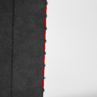
Web inspection spans a broad family of industrial quality control tasks where a continuous moving material—film, paper, metal foil, woven fabric, nonwoven, coated substrate, or printed web—is checked at full production speed. The aim is to catch surface defects, print errors, coating variations, and contamination before the material is wound or converted into finished product. Catching defects in-line removes the cost of running defective material through downstream operations and keeps faulty product from reaching the customer.
Line scan cameras are the standard imaging solution for web inspection. A line scan camera captures one line of the web per exposure cycle, building up a two-dimensional image of the web surface as the material travels past the camera. The illumination for line scan cameras has to deliver high, uniform intensity along the full width of the web in a narrow line precisely aligned with the camera’s field of view. LED line lights are the preferred source here. They give high intensity in a narrow beam, stable output over long continuous duty cycles, and precise control of the illumination geometry.
Line Scan Camera Illumination Requirements
Line scan cameras run at line rates from a few kilohertz to over 100 kHz in high-speed work. Each line exposure is correspondingly brief: at a 50 kHz line rate, each line is exposed for 20 microseconds; at 100 kHz, for 10 microseconds. The illumination has to deliver enough photons to the sensor during that short exposure to reach the target grey level in the image.
For a web moving at 300 m/min (5 m/s) with a camera resolution of 0.1 mm per pixel, the line rate needed to avoid pixel elongation in the web direction is 50,000 lines per second. The 20-microsecond exposure at this line rate squeezes the available integration time into a very small fraction of a millisecond. The illumination intensity required to reach adequate grey levels at these short exposures is very high. Line light illuminators built for web inspection have to deliver that intensity uniformly across the full web width, which may run from 200 mm to over 3000 mm.

Do you want help choosing the product?
Line Light Geometry for Web Inspection
The geometry of the line light relative to the web surface and the camera decides which defect types are detectable and which surface features create contrast in the image. The three fundamental illumination geometries used in web inspection are bright-field, dark-field, and transmitted illumination.
Bright-Field Illumination
In bright-field illumination, the line light is placed so that its specular reflection angle falls within the acceptance cone of the camera lens. The camera images the specular reflection of the illuminator off the web surface. This geometry produces high-intensity images of smooth, reflective surfaces. Defects that interrupt or disturb the specular reflection—scratches, pits, inclusions, coating voids—show up as dark features against the bright background. Bright-field illumination is the preferred geometry for inspecting smooth, reflective webs such as metal foil, glossy coated paper, and calendered film.
Dark-Field Illumination
In dark-field illumination, the line light sits at a low angle to the web surface, outside the specular reflection angle of the camera. The web background reads dark in the image because the specular reflection never enters the camera. Defects that scatter light—surface contamination, raised fibres, coating lumps, embossed features—read bright against the dark background. Dark-field illumination delivers very high contrast for surface relief defects that stay invisible in bright-field imaging.
The illumination angle for dark-field web inspection is typically 5° to 20° from the web surface plane. At these low angles, the illumination path across the web width is far longer than the working distance measured perpendicular to the web. For a web 1000 mm wide lit at 10° from the surface at a perpendicular working distance of 200 mm, the illumination path length across the web is roughly 1150 mm. The line light has to hold uniform intensity across this extended path length.
Transmitted Illumination for Transparent and Translucent Webs
For transparent and translucent webs such as clear film, thin paper, woven fabric, and nonwoven materials, transmitted illumination through the web gives the best contrast for thickness variations, inclusions, holes, and contamination. The line light sits below the web and the camera above. The transmitted light intensity varies with local web thickness and opacity, so thickness variations and inclusions show up as brightness modulations in the image.
Uniformity Specifications for Web Inspection Line Lights
Uniformity is the most critical optical specification for line lights in web inspection. Any variation in illumination intensity along the line light length shows up as a matching variation in the grey level of the camera image across the web width. That apparent grey level variation can mask real defects or trigger false defect indications across the web profile.
The uniformity requirement for web inspection line lights is usually stated as the ratio of the minimum to the maximum intensity measured across the working length at the defined working distance. For demanding web inspection, uniformity of 90% or better is required across the full web width. RODER Vision line light illuminators reach these uniformity figures through matched LED selection, precision optical design, and controlled assembly processes that keep light output consistent across the full illuminator length.
Synchronisation with Line Scan Cameras
Line scan cameras for web inspection usually run in free-running mode at a fixed line rate, or in encoder-triggered mode where each line is triggered by a pulse from a rotary encoder on a drive roll. In both cases, the illumination has to hold constant output intensity throughout the inspection run. Any variation in illumination intensity that is synchronous with the camera line rate produces periodic banding artefacts in the image that degrade defect detection.
Continuous Mode vs Strobe Mode for Line Scan
Line scan cameras for web inspection are most often used with continuous-mode illumination. The camera exposure is set by the camera’s integration time, and the illumination stays on continuously. That simplifies synchronisation because no trigger signal goes to the illuminator. The illuminator has to hold very stable output over the full duration of the inspection run, which may stretch to hours or days for large web rolls.
For very high line rate work where the required continuous-mode intensity exceeds the illuminator’s thermal rating, strobe mode is used. The illuminator is pulsed once per line, synced to the camera line trigger output, with a pulse duration equal to the camera integration time. That lets the illuminator deliver higher peak intensity during the short integration window without passing its average thermal rating. RODER Vision line light illuminators support both continuous and strobe operation.
Wavelength Selection for Web Materials
The optimum illumination wavelength for web inspection depends on the optical properties of the web material and the nature of the defects to be caught. For most surface defect detection on opaque webs, red or near-infrared illumination at 625 nm to 850 nm is preferred because it maximises signal-to-noise ratio with standard silicon line scan sensors and tones down the web texture that can mask subtle surface defects.
For colour print inspection and colour deviation detection on printed webs, white illumination with a stable colour temperature gives accurate colour rendition across the full web width. UV illumination serves the inspection of fluorescent security features on banknote paper, security printing substrates, and authentication labels in web form. Near-infrared illumination reaches through surface coatings and can reveal subsurface features in multi-layer paper and cardboard webs that stay invisible at visible wavelengths.
Thermal Stability in Long-Duration Web Inspection Runs
Web inspection lines run for extended periods without interruption. Roll changes may come every few hours, but the inspection system runs continuously between changes. The illumination has to hold stable intensity throughout the full run. Any drift in illumination intensity from LED warming during the run shows up as a gradual change in image grey level across the length of the web roll. That drift can let defects slip through at the beginning or end of the roll when the illuminator output differs from the level at which the inspection thresholds were calibrated.
RODER Vision line light illuminators build in HTTM thermal management technology. The HTTM system holds down thermal drift by controlling the LED junction temperature from the moment the illuminator is switched on, reaching thermal equilibrium quickly and keeping output stable throughout the run. That removes the need for warm-up delays before inspection can start and prevents output drift during long production runs.
Products and Technologies
RODER Vision Illuminator Families for Web and Line Scan Inspection
The RODER Vision product families below suit line scan web inspection in continuous production environments.

DL5 — High Intensity LED Matrix
High peak intensity for line scan web inspection at high line rates. Bar format for wide web coverage. Bright-field and dark-field configurations. Multi-wavelength options.

DL6 — High Density LED Matrix
HTTM thermal management for stable output in long production runs. Multi-wavelength. Continuous and strobe modes. Large bar format for wide web widths.

BL3 — LED Backlights
Transmitted illumination for transparent and translucent web inspection. High uniformity for accurate thickness and inclusion detection. Multiple wavelengths and format sizes.

FD2 — Flat Dome LED Illuminators
Diffuse illumination for printed web colour inspection. Clears specular reflections on gloss-coated substrates. Uniform background for accurate colour and density measurement.
Frequently Asked Questions
The best geometry depends on the web material and the defect types. Bright-field illumination suits smooth, reflective webs where defects show up as dark spots interrupting the specular reflection. Dark-field illumination at low angles suits surface relief defects such as contamination and raised fibres. Transmitted illumination is used for transparent and translucent webs to catch thickness variations and inclusions.
For demanding web inspection, uniformity of 90 percent or better is required across the full web width at the defined working distance. Lower uniformity produces grey level variation across the image width that can mask real defects or trigger false indications. Verify the uniformity with a calibrated measurement setup at the actual working distance before accepting the illuminator.
Continuous mode is the standard pick for line scan web inspection because it simplifies synchronisation and needs no trigger signal to the illuminator. Strobe mode is used when the required continuous-mode intensity exceeds the illuminator thermal rating, which happens at very high line rates. RODER Vision line light illuminators support both modes.
Thermal drift makes the illumination intensity shift as the LED junction temperature stabilises after switch-on. It shows up as a gradual change in image grey level across the length of the inspected roll. Defects may slip through at the start or end of the roll when output differs from the calibration level. HTTM thermal management in RODER Vision illuminators holds this drift down for stable output through long runs.
White illumination serves colour print inspection and colour deviation detection on printed webs. Red or near-infrared illumination maximises signal-to-noise for surface defect detection in monochrome inspection with silicon line scan sensors. UV illumination serves fluorescent security feature inspection on security paper and authentication substrates. Near-infrared illumination can reveal subsurface features in multi-layer paper and cardboard webs.
Contacts & Information
Contact for general information : info@roder.it
Systems and Sensor Integration Partner : www.roder.it
RODER Artificial Vision Division : www.rodervision.com
RODER Instruments Division : www.innovacheck.com
More information about RODER VISION : about us
The information on this website is provided for informational purposes only. Although it has been prepared with the utmost care, it does not constitute a contractual offer or a binding commitment to supply. It may contain transcription, translation, or typographical errors. For precise and up-to-date information, please contact our company directly.
Please note: Some images on this website have been intentionally generated using Artificial Intelligence (AI). This is due to the fact that, for many applications and projects, it is not possible to disclose photographs of the actual installation or system due to confidentiality agreements, contractual clauses, and Non-Disclosure Agreements (NDAs).
Related topics :
 Telecentric Backlighting for High-Precision Fastener and Screw Inspection
 Label Inspection with Diffuse Lighting: Catching Creases and Print Errors
 Bright LED Bar Light Illumination for Scanning Oversized Parcels on Logistics Conveyors
 UV LED Lighting for Fluorescent Leak Detection and Security Marker Inspection