Many surface defects are simply invisible under standard front-lighting or diffuse illumination. Scratches, micro-cracks, engraving marks, surface roughness variations, and fine particles can all fail to produce any detectable contrast when lit from above. Darkfield illumination clears this hurdle by changing the geometry of the light source rather than its intensity or wavelength.
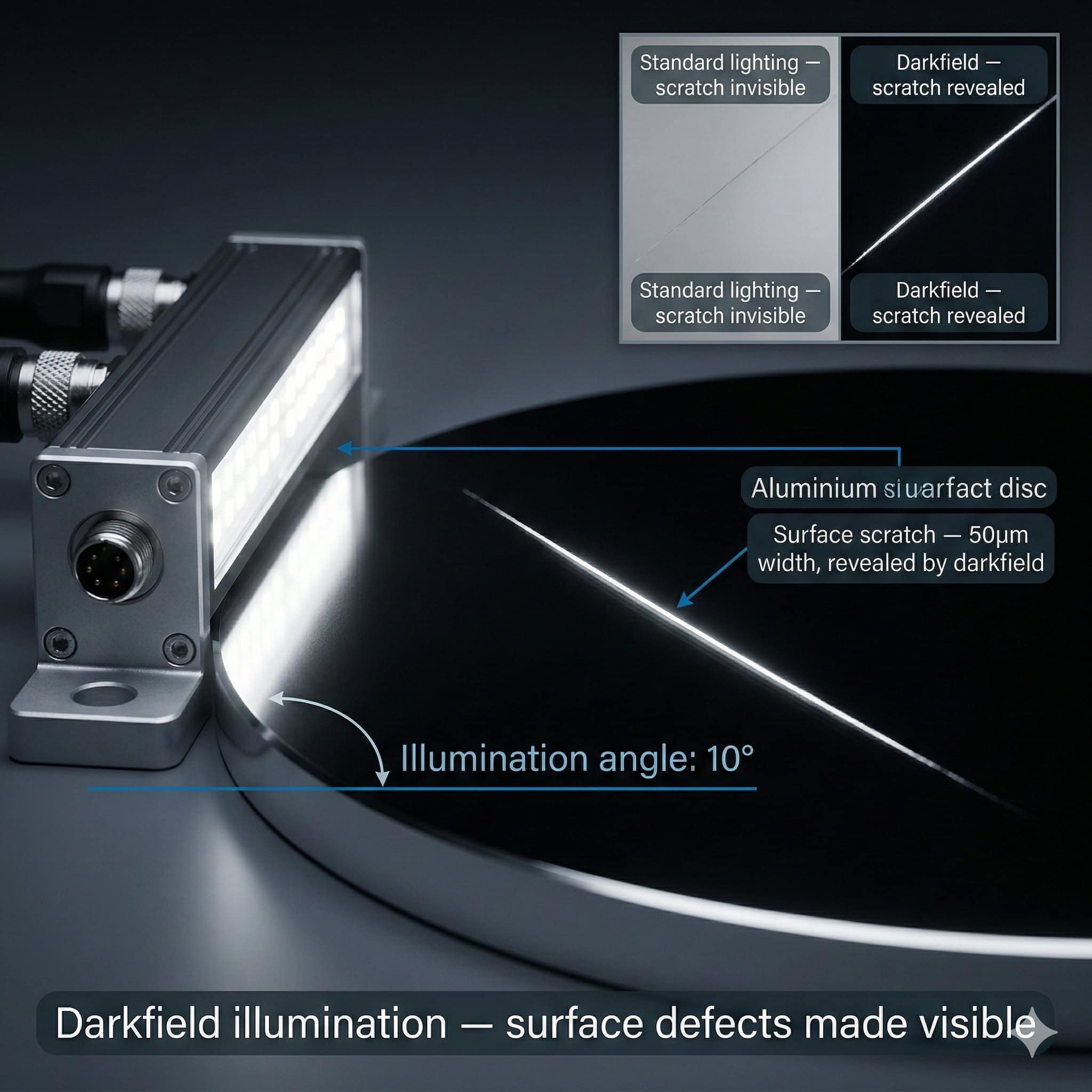
Darkfield illumination is a direct illumination technique built on grazing incidence. The light source sits at a very low angle to the surface plane, typically between 5° and 20° from horizontal. At such shallow angles, the geometry of reflection is radically different from conventional front-lighting, and the resulting images reveal categories of surface information completely hidden under standard illumination.
1. Physics of Darkfield Illumination
To see why darkfield illumination works, consider what happens when light strikes a smooth surface at a very low angle. A smooth, flat surface lit at grazing incidence reflects virtually all of the incident light at an equal and opposite grazing angle. The reflected beam travels away from the surface at the same low angle and never enters the camera lens, which sits above the surface looking downward. The smooth surface therefore reads dark in the camera image.
Any surface feature that departs from the smooth plane scatters some of the incident light in directions other than the specular reflection direction. Some of that scattered light travels upward at angles that do enter the camera lens, so the feature reads bright against the dark background. That is the contrast mechanism of darkfield illumination: defects and surface features read bright, while the smooth background reads dark.

Do you want help choosing the product?
Why Darkfield Beats Bright-Field for Fine Defects
Under conventional front-lighting (bright-field), a small scratch on a smooth surface cuts the local reflectance by a small percentage. The signal difference between the scratched area and the surrounding smooth surface may be only a few grey levels in the camera image. Detecting that reliably with an image processing algorithm calls for a very high signal-to-noise ratio and careful threshold selection.
Under darkfield illumination, the same scratch reads as a bright feature against a completely dark background. The signal-to-background ratio is very high, and the grey level of the scratch can run many times above the grey level of the smooth background. That makes threshold selection robust and detection reliability very high, even for very fine or shallow defects that would be undetectable under any bright-field technique.
Shadow Enhancement for Surface Relief
Darkfield illumination also lifts the visibility of raised surface features through shadow formation. When the light arrives at a very low angle, any raised feature casts a shadow far longer than the feature height. A raised burr 10 micrometres high lit at 10° from horizontal casts a shadow roughly 57 micrometres long. That shadow magnification makes even very small raised features easy to see and measure.
This shadow enhancement serves applications including: detection of raised burrs on machined edges, verification of embossed or debossed patterns on packaging, detection of surface contamination particles, and measurement of surface roughness profiles. The shadow length ties directly to the feature height and the illumination angle, which allows quantitative height estimation from shadow measurement.
2. Ideal Surfaces and Defects for Darkfield Inspection
Darkfield illumination is especially effective on smooth or polished surfaces where the background reflectance is high and the defects cause localised scattering. The technique is weaker on rough or matt surfaces where the background scatters light even in defect-free areas, narrowing the contrast between defective and non-defective regions.
Metal Surfaces
Polished and machined metal surfaces are among the most common applications for darkfield illumination. Scratches from handling, tool marks from machining, micro-cracks from forming or heat treatment, and surface particles from the process all read with high contrast under darkfield. The technique serves 100% inline inspection of turned components, ground surfaces, stamped parts, and precision-machined components in automotive, aerospace, and general engineering.
Glass and Optical Components
Glass surfaces are highly specular. Under bright-field illumination, defects on glass surfaces can be masked by reflections and transmission effects. Under darkfield illumination at grazing incidence, scratches, chips, surface particles, and coating defects on glass surfaces read as bright features against a dark background at high contrast. That makes darkfield the standard technique for flat glass inspection, optical element quality control, and inspection of glass packaging.
Plastic and Coated Surfaces
Injection-moulded plastic parts with glossy or semi-gloss surfaces, coated components, and film surfaces can all be inspected with darkfield illumination. The technique works well for catching flow lines, sink marks, surface contamination, and coating non-uniformities on plastic parts. The illumination wavelength should be chosen to suit the reflectance characteristics of the plastic or coating material.
Semiconductor Wafers and Electronic Components
Semiconductor wafer inspection is one of the most demanding darkfield applications. Wafer surfaces have to be completely free of particles, scratches, and surface defects down to sub-micrometre dimensions. Darkfield illumination at very low angles, paired with high-resolution optics and sensitive cameras, allows detection of defects that are otherwise invisible. Similar requirements apply to the inspection of bare PCB surfaces, ceramic substrates, and precision electronic components.
3. Illumination Angle Selection
The illumination angle in darkfield applications is the most important design parameter. It sets the contrast of the smooth background, the shadow magnification of raised features, and the sensitivity to different defect types. The best angle depends on the surface characteristics of the object and the nature of the defects to be caught.
Very Low Angles: 5° to 10°
Very low illumination angles (5° to 10° from horizontal) give the highest shadow magnification and the darkest background on smooth specular surfaces. They serve the detection of very shallow defects such as fine scratches, micro-cracks, and surface roughness variations on highly polished surfaces. The working distance between the illuminator and the object surface is usually short at these angles, which has to be allowed for in the mechanical design of the inspection cell.
Moderate Low Angles: 15° to 25°
Moderate low angles (15° to 25°) strike a balance between background darkness and shadow length. They work well for catching surface particles, raised burrs, engraving, and surface texture variations on machined or semi-polished surfaces. This angle range is the most widely used in general industrial inspection, giving good contrast across a wide range of surface finishes without the tight mechanical constraints of very low angles.
Ring and Multi-Directional Darkfield Illuminators
A ring illuminator set at a low angle gives darkfield illumination from all azimuthal directions at once. That makes sure scratches and linear features in any orientation on the surface are caught equally. A scratch running parallel to the direction of a single-direction darkfield beam may not scatter much light and could be missed. A ring geometry clears this directionality dependence.
RODER Vision DC-series low-angle ring illuminators are designed specifically for darkfield surface inspection. The ring geometry gives omnidirectional low-angle illumination, and multiple illumination angles are available to suit different surface finishes and defect types.
4. Integration Tips for Darkfield Inspection Systems
Darkfield illumination systems call for careful mechanical and optical design to reach reliable, repeatable inspection results. The guidelines below cover the most important integration considerations.
Object Flatness and Positioning
The performance of darkfield illumination is sensitive to the flatness and positioning of the object surface. A tilted or warped surface changes the effective illumination angle across the field of view. That can leave the background looking non-uniform, with some areas darker and others showing unwanted reflections. Object positioning fixtures should hold the part flat and at a consistent height relative to the illuminator. Height variation of more than 1 to 2 mm can degrade contrast in low-angle darkfield configurations.
Ambient Light Rejection
Darkfield inspection cells are especially sensitive to ambient light contamination. The dark background that makes darkfield so effective is only reachable when no stray light reaches the surface from other directions. Even a small amount of overhead ambient light on the object surface brightens the background and cuts defect contrast. Darkfield inspection cells should be enclosed or shielded to shut out ambient light. Strobe mode operation with short exposure times adds further rejection of ambient light from factory sources.
Camera Settings and Exposure Optimisation
Because the background in a darkfield image is very dark, the camera exposure has to be set to make the defect signals visible without saturating them. The best exposure balances the brightness of the defect signals against the noise floor of the camera sensor. Strobe mode illumination with a high peak intensity allows very short exposure times, which cuts motion blur on moving objects and improves ambient light rejection at the same time.
RODER Vision DL5 and DC6 series illuminators support strobe mode operation with peak intensities many times higher than their continuous-mode values. This pairing of short exposure and high peak intensity is the standard approach for high-speed darkfield inspection on production lines.
Products and Technologies
RODER Vision Illuminator Families for Darkfield Inspection
The RODER Vision product families below suit darkfield surface inspection across a range of surface types, object sizes, and line speeds.

DC6 — High Density LED Ring
Low-angle omnidirectional ring illumination for darkfield surface inspection. Catches scratches whatever their orientation. Multi-wavelength. Strobe compatible.

DL5 — High Intensity LED Matrix
Very high peak intensity in strobe mode. Ideal for directional darkfield at defined angles. High-speed conveyor inspection with short exposure times.

DL6 — High Density LED Matrix
High density matrix for directional low-angle darkfield. HTTM thermal stability for 24/7 production. Multi-wavelength for surface-specific contrast.

BL3 — LED Backlight Series
High-uniformity backlight used with darkfield front illumination for dual-mode defect detection on transparent and semi-transparent parts.
Frequently Asked Questions
Darkfield illumination uses grazing-incidence light directed at a very low angle to the surface. The smooth surface reflects light away from the camera and reads dark. Surface features that scatter light, such as scratches, particles, and raised edges, read bright against the dark background. This contrast reversal compared with standard illumination makes fine surface defects visible that would otherwise be undetectable.
Darkfield illumination is most effective for scratches, micro-cracks, surface particles, raised burrs, engraving marks, and surface roughness variations. It works best on smooth or polished surfaces such as metals, glass, gloss-finish plastics, and semiconductor wafers. On rough or matt surfaces, the background scattering narrows contrast and darkfield becomes less effective.
The best angle depends on the surface and defect type. Very low angles (5 to 10 degrees from horizontal) maximise shadow magnification and background darkness for polished surfaces with very fine defects. Moderate low angles (15 to 25 degrees) are more practical for general industrial inspection and work well across a wider range of surface finishes. A ring illuminator at the right angle gives omnidirectional darkfield detection regardless of defect orientation.
The effectiveness of darkfield illumination depends on the smooth surface background being as dark as possible. Any ambient light reaching the surface from directions other than the darkfield source brightens the background and cuts the contrast of the defect signal. Even small amounts of overhead ambient light can degrade detection noticeably. Darkfield inspection cells should be enclosed to shut out ambient light, and strobe operation with short exposure times adds further rejection.
Yes. Darkfield illumination is often paired with bright-field or backlight illumination in systems that have to catch multiple defect types. Sequential illumination, firing different illuminators in sequence while the camera takes separate exposures, lets the same camera station capture both a darkfield surface image and a bright-field or backlight image of the same part. Each image is analysed for the defect types best suited to that illumination mode.
Contacts & Information
Contact for general information : info@roder.it
Systems and Sensor Integration Partner : www.roder.it
RODER Artificial Vision Division : www.rodervision.com
RODER Instruments Division : www.innovacheck.com
More information about RODER VISION : about us
The information on this website is provided for informational purposes only. Although it has been prepared with the utmost care, it does not constitute a contractual offer or a binding commitment to supply. It may contain transcription, translation, or typographical errors. For precise and up-to-date information, please contact our company directly.
Please note: Some images on this website have been intentionally generated using Artificial Intelligence (AI). This is due to the fact that, for many applications and projects, it is not possible to disclose photographs of the actual installation or system due to confidentiality agreements, contractual clauses, and Non-Disclosure Agreements (NDAs).
