Fastener dimensional inspection is one of the most demanding measurement tasks in industrial machine vision. Screws, bolts, nuts, rivets, and precision turned parts must conform to tight dimensional tolerances. Thread pitch, thread profile, shank diameter, head height, and overall length must all be measured with sub-pixel accuracy at production-line speeds. A single oversized or undersized fastener delivered to an assembly line can cause assembly failures, torque specification violations, or field failures in safety-critical applications.
The illumination system is the foundation of any high-accuracy fastener measurement vision system. Sub-pixel edge detection depends entirely on producing an image with a sharp, well-defined edge at the fastener boundary. This requires backlight illumination with high uniformity, high intensity, and a diffusion profile optimised to minimise penumbra. Any compromise in illumination quality translates directly into measurement uncertainty.
Why Backlight Illumination is Essential for Fastener Measurement
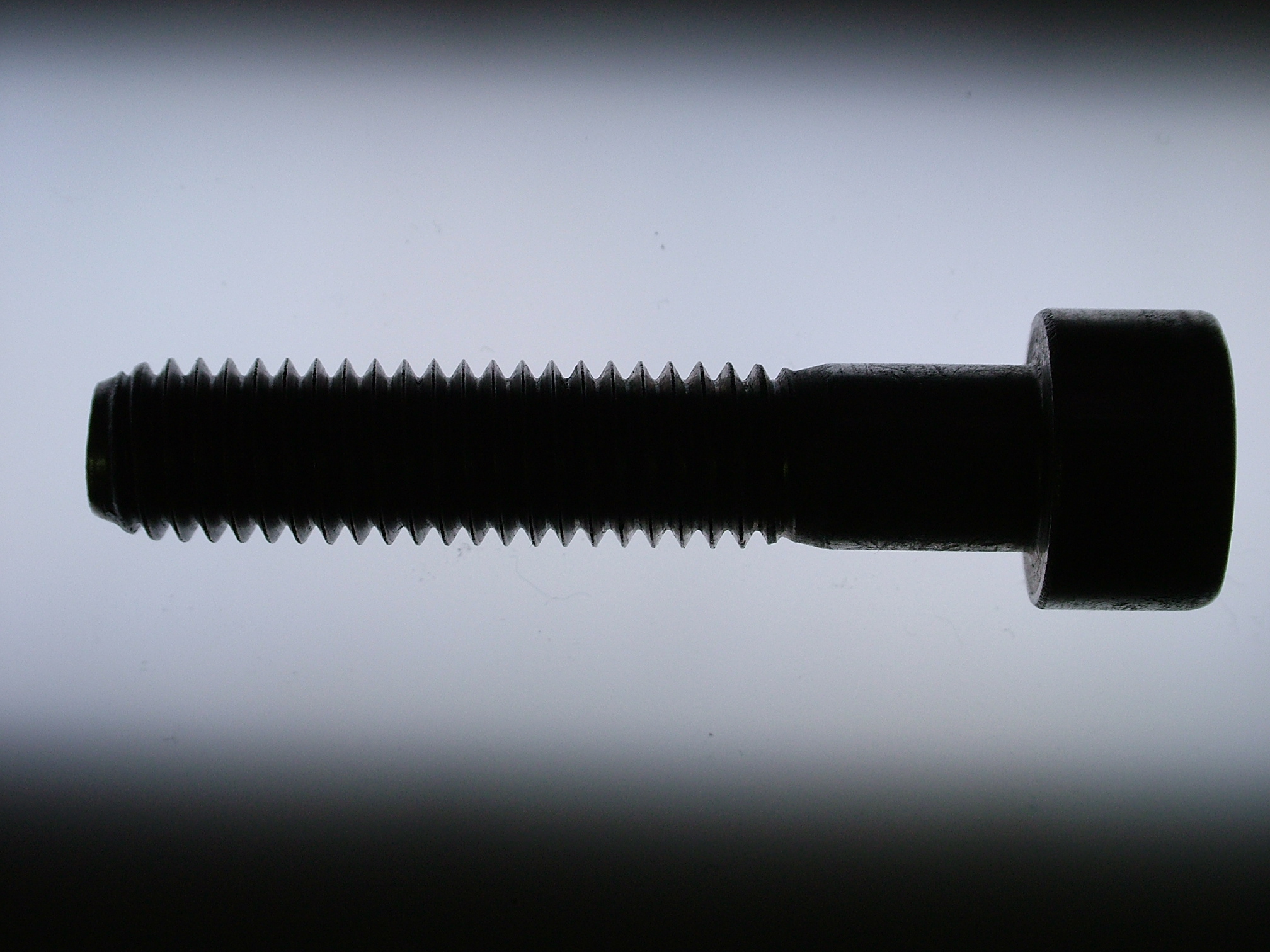
Dimensional measurement of fasteners by machine vision relies on detecting the silhouette of the part against a bright, uniform background. The camera images the shadow of the fastener projected onto the illuminated background. The measurement algorithms detect the edges of this silhouette and calculate dimensions from the pixel coordinates of the edge positions.
This approach requires a backlight that delivers a uniform, bright background completely free of hot spots, dark patches, or gradients. Any non-uniformity in the background introduces a position-dependent threshold in the edge detection algorithm. The apparent edge position shifts depending on the local background brightness, adding a systematic error to the measurement that is difficult to calibrate out.

Do you want help choosing the product?
RODER Vision BL-series backlight illuminators are designed specifically for metrology applications. The active area uniformity specification is 95% or better across the full illuminated surface. This level of uniformity maintains consistent edge detection thresholds across the entire field of view and allows accurate dimensional measurement at any position within the field.
Telecentric Illumination and Telecentric Optics
In standard vision systems, the apparent size of an object in the image depends on its distance from the camera lens. An object that is slightly closer to the lens appears larger; an object slightly further away appears smaller. For dimensional measurement, this means that any variation in the distance between the part and the lens — due to part height variation, conveyor vibration, or mechanical tolerances in the fixturing — introduces a measurement error.
Telecentric lenses solve this problem by collecting only the rays that are parallel to the optical axis. An object that moves toward or away from the lens produces no change in image magnification within the depth of field of the telecentric lens. This makes telecentric optics the standard choice for dimensional measurement applications where high accuracy is required.
Illumination Requirements for Telecentric Systems
Telecentric lenses have a specific requirement for the illumination: the backlight must produce light that is substantially collimated — that is, the light rays must be parallel and directed along the optical axis. A non-collimated backlight produces a penumbra at the edge of the silhouette. The penumbra is a blurred transition zone between the bright background and the dark silhouette of the part. The width of the penumbra determines the minimum edge detection uncertainty.
For non-critical dimensional measurements, a standard high-uniformity backlight with a good diffuser produces a penumbra that is small enough for the required accuracy. For the most demanding measurements — thread profile at high magnification, or shank diameter to ±1 micrometre accuracy — a telecentric backlight is used. A telecentric backlight incorporates a collimating lens that produces parallel light rays at the exit surface. This minimises the penumbra and produces the sharpest possible edge in the camera image.
Thread Profile and Pitch Measurement
Thread inspection is the most geometrically complex measurement task on a fastener. The thread profile includes the thread pitch, thread angle, major diameter, minor diameter, and thread form. All of these parameters must be within specification for the fastener to function correctly in its mating component.
Imaging Geometry for Thread Measurement
Thread profile measurement requires the screw to be oriented with its axis perpendicular to the optical axis of the camera. The backlight illuminates the screw from behind. The camera images the silhouette of the thread profile. The thread crests and roots appear as periodic peaks and valleys in the silhouette edge profile.
The magnification must be sufficient to resolve the individual thread features. For M3 screws with a 0.5 mm pitch, a magnification that maps each thread pitch to at least 20 pixels is required for accurate pitch and angle measurement. A higher magnification of 40 to 80 pixels per pitch improves measurement precision but reduces the number of threads visible in the field of view.
Illumination Angle and Thread Silhouette Quality
For thread silhouette imaging, the backlight must be positioned directly behind the thread axis. Any angular offset between the backlight and the camera axis causes the thread flanks to be partially illuminated from the front, which reduces the sharpness of the silhouette edge at the thread root. The backlight must be centred precisely behind the measurement zone.
The illumination wavelength also affects thread measurement accuracy. Shorter wavelengths produce sharper diffractive edges in the silhouette image. Blue (470 nm) or green (525 nm) illumination gives sharper edges than red (617 nm) for the same optical system. For the most demanding thread profile measurements, monochromatic blue or green backlight illumination is preferred over white or red.
Head Geometry and Drive Recess Inspection
Screw head geometry inspection includes head diameter, head height, and the integrity of the drive recess. Drive recesses — Phillips, Torx, hexagon socket, slotted, and others — must be within specification depth and free from damage or deformation. A damaged drive recess causes assembly failures during automated screwdriving and can cause screwdriver bit breakage.
Top-View Illumination for Drive Recess Inspection
Drive recess inspection requires a top-view camera looking down at the screw head. Coaxial illumination is the most effective technique for drive recess inspection. Coaxial light travels along the optical axis, enters the drive recess, and reflects from the recess walls and bottom. The recess profile appears as a pattern of bright and shadow regions that is characteristic of the recess geometry and depth.
Darkfield illumination at shallow angles is effective for detecting deformation or damage at the rim of the drive recess. Burrs, rolled edges, and surface damage that would be invisible under coaxial illumination scatter light under darkfield conditions and appear as bright anomalies against the dark head surface.
Ring Illumination for Head Peripheral Features
Ring illumination from above the screw head provides uniform front illumination for inspecting the peripheral geometry of the head, including flange diameter, washer presence, and surface marking. Ring illumination at a moderate angle produces a bright, even image of the top surface of the screw head that is suitable for marking reading, surface finish verification, and geometric measurement of the head perimeter.
Length, Shank Diameter, and Point Measurement
Overall fastener length, shank diameter, and point geometry are the three remaining critical dimensional parameters for most screw types. All three are measured from the side-view silhouette image using backlight illumination.
Overall length is measured as the distance between the top of the head and the tip of the point in the silhouette image. The measurement accuracy depends on the magnification calibration and the uniformity of the backlight. Shank diameter is measured at multiple positions along the shank to check for taper, ovality, or diameter variation. Point geometry — taper angle, point length, and point symmetry — is measured from the silhouette of the tip region.
The part must be held with its axis precisely perpendicular to the camera optical axis during measurement. Any tilt of the fastener axis produces a foreshortening of the silhouette that introduces an error in both length and diameter measurements. Part presentation fixtures must constrain the angular position of the fastener to within 0.1° for high-accuracy length measurements.
Integration Considerations for Inline Fastener Inspection
Inline fastener inspection systems must handle parts presented by bowl feeders, vibratory tracks, or conveyor belts at high throughput rates. The illumination system must be compatible with these presentation mechanisms and with the triggering requirements of the vision system.
Strobe mode operation is essential for inline fastener inspection. The parts move continuously on the track or conveyor. The illuminator is pulsed at a very short duration — typically 10 to 100 microseconds — synchronised with the camera exposure. The short pulse duration freezes the motion of the fastener completely, regardless of the line speed. RODER Vision BL3 backlight illuminators support strobe triggering with peak intensities several times higher than the continuous mode output, providing both motion-free images and high contrast at high production rates.
Products and Technologies
RODER Vision Illuminator Families for Fastener Inspection
The following RODER Vision product families are specifically suited for fastener dimensional measurement and drive recess inspection applications.

BL3 — LED Backlight Series
High-uniformity backlight for fastener silhouette measurement. 95%+ uniformity. Strobe trigger for motion-free images. Multi-wavelength including blue for sharp edges.

DC6 — High Density LED Ring
Ring illumination for screw head top-view inspection: drive recess, head geometry, and surface marking. Near-coaxial angle option. Multi-wavelength.

DL5 — High Intensity LED Matrix
High peak intensity for darkfield screw head inspection: burr detection, drive recess damage, surface defects. Very short strobe pulses for high-speed part presentation.

DL6 — High Density LED Matrix
Direct matrix illumination for fastener head marking and serialisation reading. HTTM thermal stability for continuous 24/7 inspection lines. UV option for ink traceability.
Frequently Asked Questions
Backlight illumination creates a high-contrast silhouette of the fastener against a bright, uniform background. The camera images the shadow of the part. Dimensional measurement algorithms detect the silhouette edges with sub-pixel accuracy. This approach is independent of the surface finish or colour of the fastener and provides the highest accuracy for length, diameter, and thread profile measurement.
A telecentric backlight incorporates a collimating lens that produces parallel light rays. This minimises the penumbra at the edge of the fastener silhouette and produces the sharpest possible edge in the camera image. It is needed for the most demanding dimensional measurements where standard backlights produce a penumbra that is too wide for the required measurement accuracy.
Shorter wavelengths produce sharper diffractive edges in the silhouette image. Blue (470 nm) or green (525 nm) illumination gives sharper edges than red or white for the same optical system. For the most demanding thread profile measurements at high magnification, monochromatic blue or green backlight illumination is preferred.
Drive recess inspection requires a top-view camera and coaxial illumination. Coaxial light travels along the optical axis, enters the recess, and produces a characteristic pattern of bright and shadow regions from which recess depth and geometry are assessed. Darkfield illumination at shallow angles detects burrs, rolled edges, and surface damage at the rim of the recess that coaxial illumination would miss.
Strobe mode illumination with very short pulse durations (10 to 100 microseconds) synchronised with the camera exposure freezes the motion of the fastener completely. RODER Vision BL3 and DL5 series illuminators support strobe triggering with peak intensities several times higher than continuous mode output, providing both motion-free images and high contrast at high production rates.
More information and contacts
Systems and Sensor Integration Partners : www.roder.it
Artificial Vision Division : www.rodervision.com
More information about RODER VISION : about us
Contact for general information : info@roder.it
The information on this website is provided for information purposes only. Although it has been prepared with the utmost care, it does not constitute a contractual offer or a binding commitment to supply. It may contain transcription, translation or typographical errors. For precise and up-to-date information, please contact our company directly.
Related topics :
 Precision Bottle Cap Inspection: Machine Vision & LED Lighting Solutions
 The Advantages of LED Backlighting in Precise Dimensional Measurement
 Logistics Automation: High-Intensity Bar Lights for Large Parcel Scanning
 Line Lights for Web Inspection: Maximizing Throughput in Continuous Production
 UV LED Illumination for Fluorescent Leak Detection and Security Markers